Beautiful additions and upgrades to your home may increase the value, while providing tax incentives for you as you carefully plan your home electrical wiring diagrams.
Code requirements along with energy efficient specifications can enhance your energy saving design and provide safety features to protect you and your family while enjoying your home project.
Fully explained home electrical wiring diagrams with pictures including an actual set of house plans that I used to wire a new home. Choose from the list below to navigate to various rooms of this home*.
When planning a home improvement project of any size special attention should be given to the electrical systems. Replacing worn out outlets and switches will help, but look at your options for higher efficiency lighting and code upgrades too.
In electronics, Rectifier circuit is the most used circuit because almost every electronic appliance operates on DC (Direct Current) but the availability of the DC Sources are limited such as electrical outlets in our homes provide AC (Alternating current). The rectifier is the perfect candidate for this job in industries & Home to convert AC into DC. Even our cell phone chargers use rectifiers to convert the AC from our home outlets to DC. Different types of Rectifiers are used for specific applications.
Usually, the types of Rectifiers are classified based on their output. In this article, we will discuss many types of Rectifiers such as:
In our step by step electrical wiring installation tutorials series, We will show how to wire and connect single phase and three phase automatic and manual changeover and transfer switches to the home distribution board to use the backup power supply such us batteries power with UPS and inverters or generator power in case of emergency breakdown and power outage. Now let’s begin as follow.
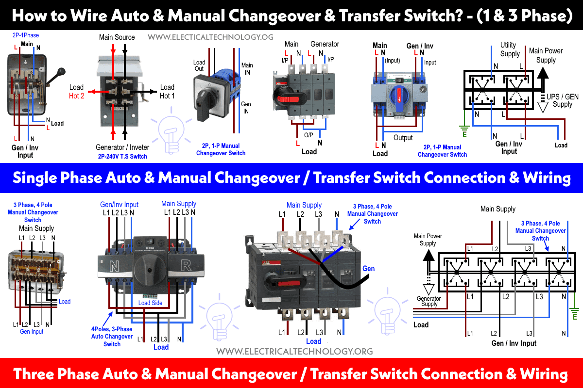
The following fig 1 shows different single phase and three phase connections for manual and automatic changeover and transfer switches. Lets explain one by one in detail as follow.
Click image to enlarge
How to Wire Automatic & Manual Changeover & Transfer Switch? – Single & Three Phase
How to Wire Single Phase Manual Transfer / Changeover Switch?
In fig 2, different connection and wiring diagrams are shown for a two pole, single phase manual changeover switch. The upper portion of the changeover switch is directly connected to the main power supply while the lower first and right connections slots are connected to the backup power supply like generator or inverter. The left side of lower slots are connected to the main board as load.
In case of power failure, the manual changeover switch can be changed to to the generator / inverter position. This way, power supply will continue to the load points through the inverter or generator. When power supply restores from the power house, simply switch back the changeover switch position to the “Main Power Supply”.
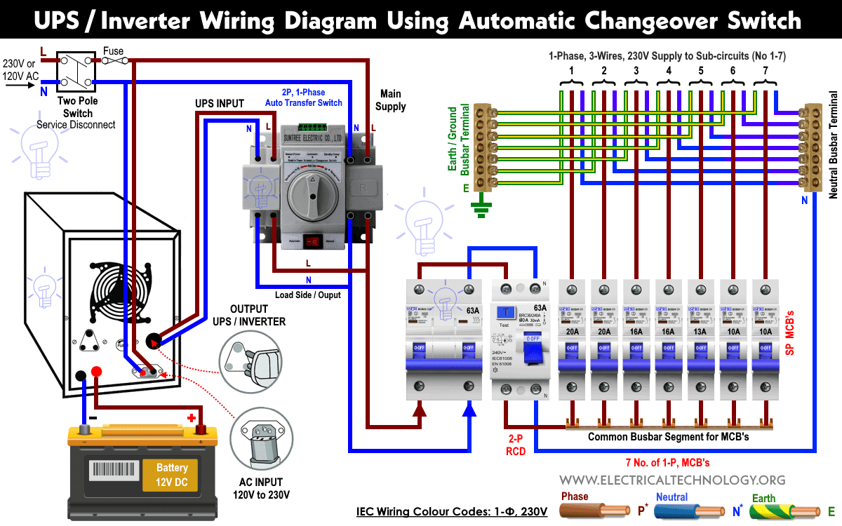
How to Connect Single Phase Automatic Changeover / Transfer Switch (ATS) ?
If you are tired of manual operation of changeover switches, ATS is the best alternative to use then. In the following fig 3, the backup power of batteries is connected to main distribution board through 2-Pole, single phase automatic changeover or transfer switch (ATS) and UPS / Inverter.
The working and operation of this circuit as same as above expect the automatic changeover switch (ATS) will detect the utility power when restores from the power house and automatically transfer from the Generator / Inverter to the Main Power supply. In case when utility power is not available, the ATS will transfer the switching position to the Inverter, hence electrical appliances will be still in operation mode without interruption through the stored power in the batteries.
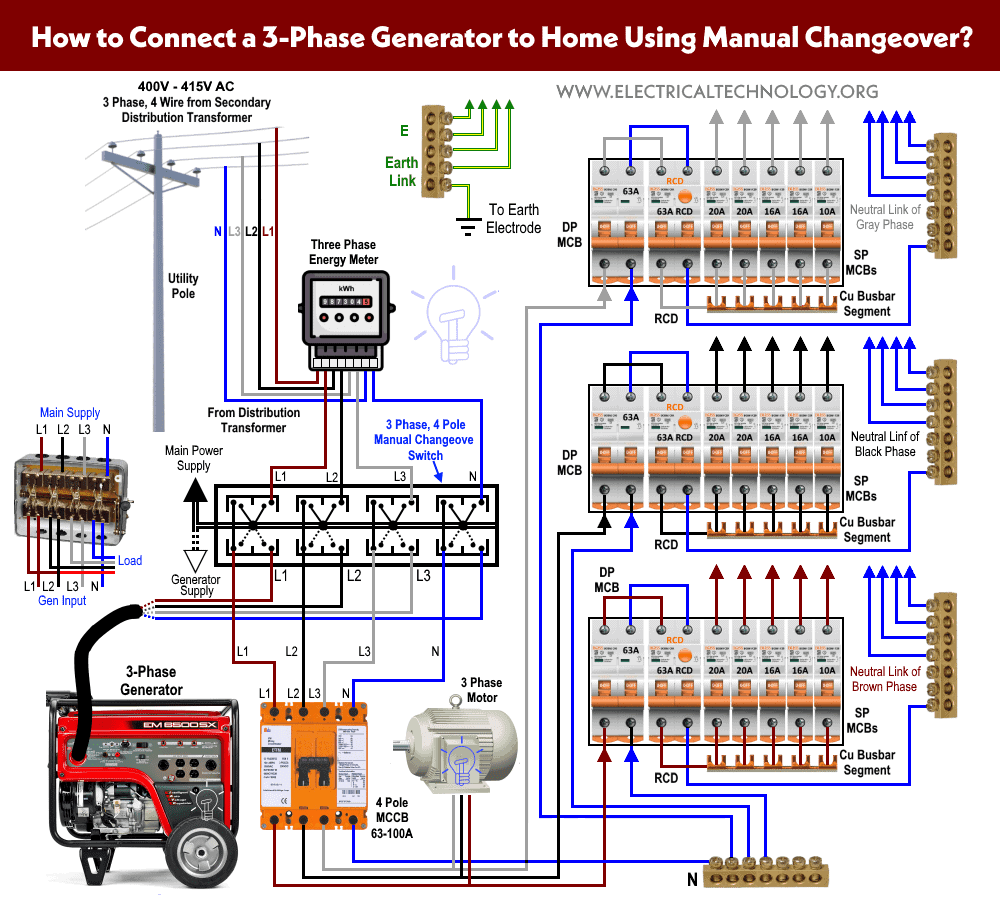
How to Wire Three Phase Manual Changeover/Transfer Switch?
Fig 4 shows that how to wire a four poles, three phase manual changeover switch to the main distribution board. This is the same connection as we discussed above for single phase wiring expect that there are three phase wires instead of line and neutral.
The three phase utility power as (L1, L2, L3 & N) are directly connected to the upper side of manual changeover switch, while the backup power of three phase generator is connected to the first four (right) slots of at lower side. The left side four slots connection points are connected to the load then.
Since the operation is manual, You have to change the changeover lever to the appropriate position manually to restore the power i.e. Change the lever position the “Generator Supply” when main power is not available and then back to the “Main Power” when utility power restores.
How to Install Three Phase Automatic Transfer/Changeover Switch?
Fig 5 shows 4-Poles, 3-Phase automatic transfer switch (ATS) connection to the main distribution board. All the wiring connections are same as above for manual operation of three phase changeover switch but the switching operation is automatic.
In case of emergency breakdown, the automatic transfer switch will automatically divert the switching position to the “Generator Supply” and when the main supply restores, it will transfer the power flow to the “Utility Power” when using emergency generator set for backup power..